PCB Design – Laser Tag + Led Controller
Not a lot of updates recently. I’m working on a small Halloween style game. And I’m hopeful to make something out of that. And I’m replacing a PID controller on my coffee maker, as it’s pretty bad at doing what it does. But some major updates are I’m pushing a few projects forward.
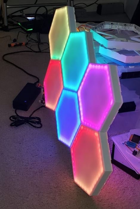
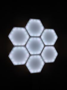
My first major PCB is a lighting controller. It’s been a while since I created my HEX light replica that syncs with my Home Assistant setup Via MQTT. I honesty fell in love with it, and never wanted to take them down to write down the schematic and design a PCB for it. But I finally broke down the circuit and have sent a PCB design off to be created.
It’s a super basic circuit with a few functions.
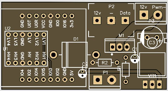
- It features an ESP32 for controlling the circuit as well as Wifi conectivity.
- It features a basic voltage regulation system that steps down 12v -> 5v -> 3.3v.
- 12v for the LEDs
- 5v for the logic level
- 3.3v for the microcontroller
- It offers both PWM and Digital LED controller. For basic lights and addressable LEDs.
- It offers some small capacitors to smooth the power delivery as well as the recommended decoupling capacitor for the ESP32.
- The traces where designed to support up to 75 watts. Which should be more than enough. An entire 300 RBG Led strip running at full power would be 7.5 amps (All LEDs on making a fake white color). My current setup with 6 hex lights uses 234 LEDs which maxes out at 5.85amps. But I have a white LED strip that only pulls 4.1 amps at max brightness. Which above 40% it’s blinding to look at. So for pure white it makes more sense to run the white leds at 2 amps.
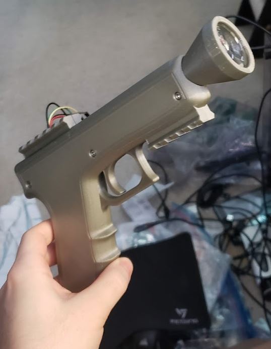
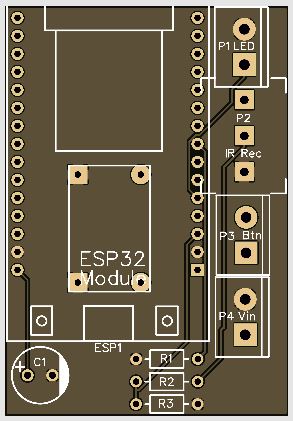
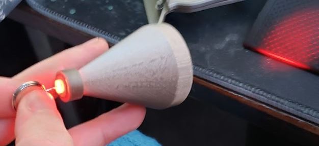
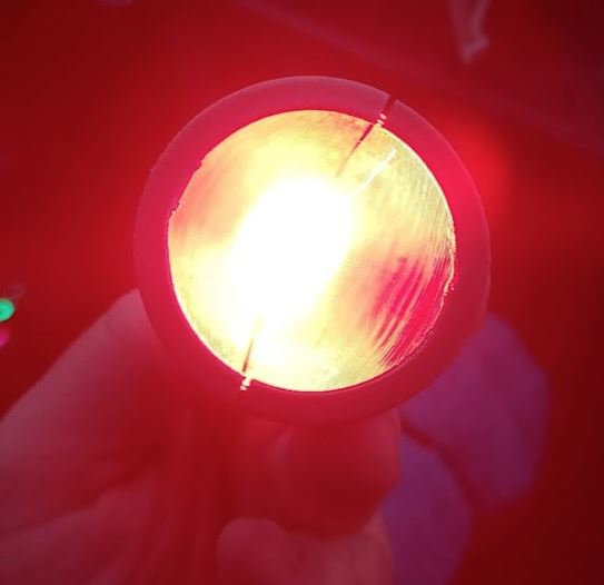
A while back I also designed a little communication protocol for a lasertag system. Pairing the IR Diode with a lens allowed me to focus the light an extend the range of the blasters by literally hundreds of feet.
I hit a stumble when my PCB was millimeters too wide with jumpers sticking off of it to fit inside of the blaster I 3d modeled. It is also designed in 4 pieces, The shell is printed in 2 halves in such a way to give it a nice smooth outside, And the led/lens holder is also printed in 2 parts which locks into the front. As this was a prototype I printed it all out at once, Later when actually testing, I will print the lens holder in orange.
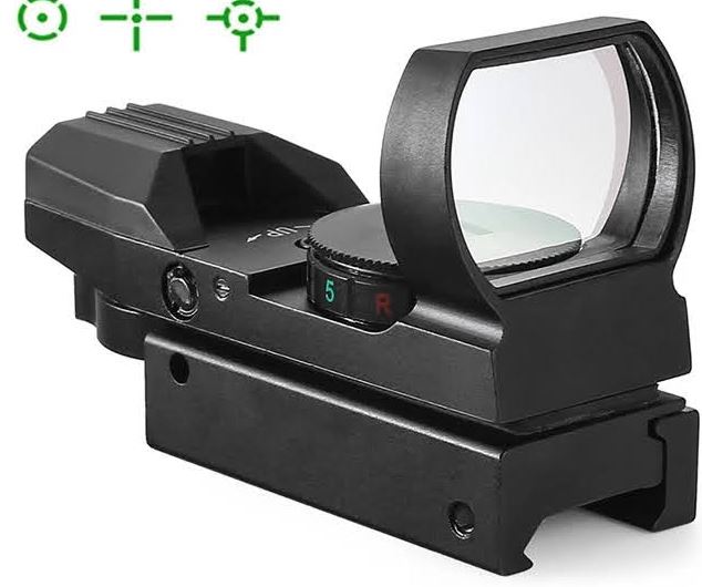
And yes, I did model picatinny rails onto the blaster to the official spec. That means I can do things like, put a red dot sight on it.
This board is far from done, But should allow me to throw together a few prototype boards and start proper testing.
Thanks for your blog, nice to read. Do not stop.