Gaggia Classic – Custom PID – V1
I’ve had a busy last few months but one of the projects I have that is nearing completion is my custom PID for my coffee machine.
This project has had a super simple premise, Keep the coffee machine’s temperature stable. Which turned out to be a lot harder than I had originally planned.
A Little Backstory
It all started when I got fed up with the archaic temperature control of the coffee machine. It was a very simple, If the Temp is at X, turn off the boiler, if it goes below x-5 turn it back on. Which works but when coffee flavor changes by temp, it meant I often had to time my shots. So that I started it just as it started heating, so it had extra heat, but not after when the water was over temp.
Later, I Decided enough was enough and I ordered a PID temperature controller from Shades of Coffee. And once that arrived I spent a good 4 hours re-wiring the coffee machine to use an external temperature sensor over the default 2 temperature switch’s. This worked a lot better but had 1 serious flaw.
I could adjust how aggressively the machine heated up to maintain more stable shots at the cost of wild overshooting (By around 10c) and extra time spent waiting for the temp to stabilize between shots.
Or I could turn down how aggressively it heated for faster time between shots, But that meant the temp would drop 15-20c while pulling a shot.
I reached out to support at Shades of Gray about that, And they very quickly replied and where super nice and knowledgeable about what I was doing and had detailed instructions on things to try. But the summary of the call was, Either you trade one luxury for the other, or you can add metal to the boiler by replacing the metal plate above the brew head with a copper one. (OR some similar metal, I don’t fully recall) Basically just add thermal mass to compensate.
Either way, After using it that way for a few months I thought to myself. “I’m an engineer! If I think it sucks, why can’t I do it better?”
Technical details on the Gaggia Classic
The Gaggia Classic runs off 2 thermostats. one that toggles a switch when it goes below 106c, the other when below around 145c. They work together to serve 2 purposes. 1 is to control the temp of the water, and the steam functions. The other is to be redundant. If the temp goes above the steam temp, it disables the heating element until it goes back down. There is also a thermal fuse mounted to the boiler.
So at a basic level to turn on the boiler’s heating element, you need to switch the Steam Relay on, AND the Boiler’s Relay. If the steam is off, the machine doesn’t turn on the heating element. And vice versa if the boiler is off it also will be off.
That is pretty much all there is to the machine. It heats and dispenses water at a fixed pressure. It has a pressure valve that releases pressure back into the reservoir if it goes above 12 bars. And there is a back pressure release valve that sends water from the shower screen to the drip tray when a shot is stopped to relieve pressure and leave you with a dryer puck. But none of this is having issues so we don’t need to touch it.
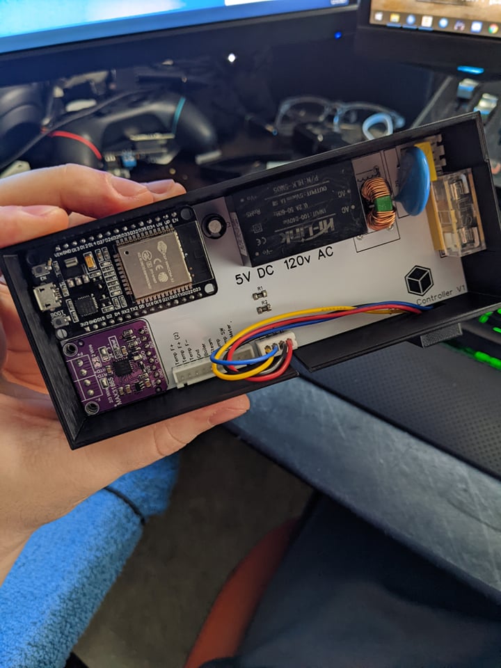
Functions of the Controller
So currently this is just past it’s proof of concept phase.
- It controls temperature (Note the high temp is because the water is lower temp than the boiler)
- It converts power to prevent needing an external power brick
- It has a Touchscreen with 2 way communication, allowing Temp Changes
- It has multiple Failsafes built in to turn off the boiler if the thermostat malfunctions.
- If checking the temp just gives an error, The system shuts down the boiler
- If the temp doesn’t change values for X checks (Depends on where it’s at in the heating process) it also shuts down.
- And it features multiple planned features if I want to put them in.
- Measuring the volume of coffee dispensed (To auto stop the shot when done)
- Detecting if the brew switch is ON. (I like the feel of a mechanical switch and decided to keep it)
- Automatically controlling the Pump (To stop a shot when the correct amount is dispensed)
- And this allows for the ability to hold off starting a shot until it’s up to temperature, and stopping the shot when done. Offering a Keurig level of usability, without the gross watered down coffee.
Cons
- The steam function has not been programed. But likely wouldn’t be hard to do.
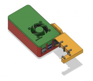
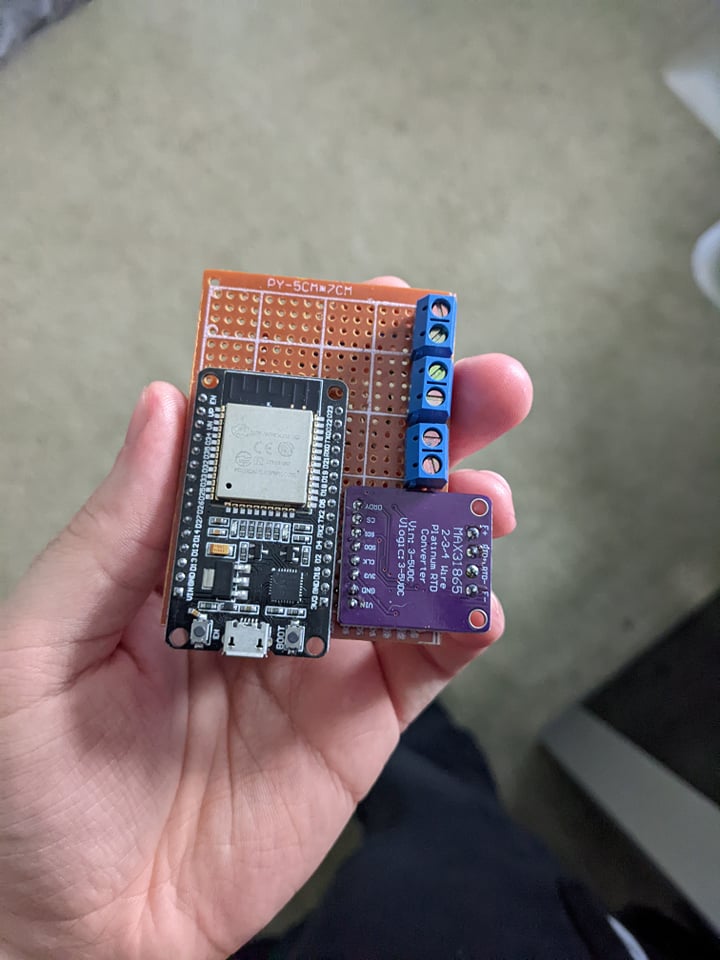
- The case is chunkier than I would like, and looking back on it, I could easily cut 25% off the PCB.
- I capitalized the V for 5v, but not 120v. And that bothers me in the most pointless way.
The Beginnings.
It all started with a proof of concept. I told myself, if I can do it better, I need to make something right now, that can out perform the built in controller. And if I can do that, I’ll invest more time into this project.
Hurdles of the project
This project had a few immediate problems, and a few that reared their ugly head as I moved forward.
- Temperature control for a coffee machine is not as easy as I hoped.
- High Freq PWM did not work on the boiler as the relay I had chosen was not flipping between states fast enough. I assume it was flipping at 0 points in the AC power sin wave. But this meant that some times when I turned on a 20% duty cycle PWM signal it would work perfectly, and other times it wouldn’t even turn the boiler on. It showed itself as my temp staying MOSTLY stable. But every once in a while it would just drop for no reason. After a quick connection to an oscilloscope. It was clear the boiler just wasn’t turning on. I ended up turning the duty cycle way down but still using the concept of PWM to drive it moving forward.
- This isn’t like heating up a sheet of metal. I can only compare this to a computer’s water cooling loop. You can hit a loop with a TON of heat right off the bat, But it can take 10-15 minutes for a temperature to stabilize. Meaning, Putting X amount of heat into at one time can give different results as another time based on the internal water temperature which we can’t directly measure with this setup. Any heating done has a lag before the temperature starts to rise. And just the same, a lag when you turn it off before you can see the temp stop rising.
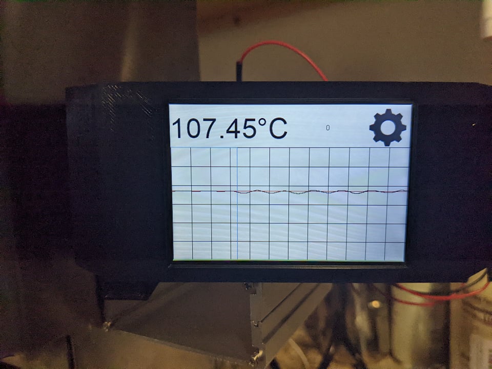
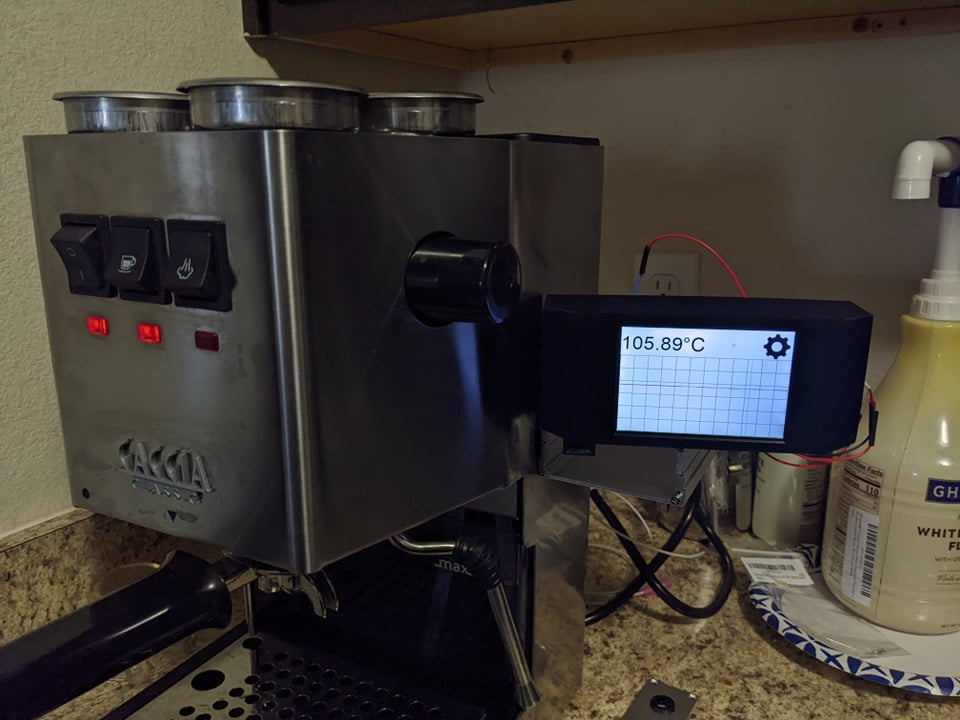
Above is a picture of the current setup. When I start a shot, you can see that blue line drop due to the temp dropping, and the heating code kicks in to try and maintain a stable temp. It’s rough, but it keeps the temp usually within 3 degrees of the setpoint.
- Bugs, lots of bugs
- The first bug I found was the screen sometimes wouldn’t get the temperature from the controller. As it asks the controller for the temp when it turns on, and again if it failed to get it later. This allows the screen to display the current setpoint without needing to cycle through numbers to change the temp. After a few days of use it just stopped working. I had built failsafes in and I had NO IDEA why it stopped working. I knew the code was solid, so I didn’t even check. While re-wiring the system for the PCB I noticed a little issue.
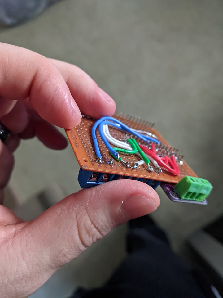
The solder connection of the TX pin on the screen had come loose. Ironically the code was so sound that even with that connection loose, the device was almost fully functional. Minus setting temp on the screen.
2. The next Bug I found was with the little clamping connections.
These have a few massive drawbacks. 1, they don’t have springs for tension, so if the wire is compressed over time it will come loose. 2, They don’t work with stranded wire, which was 100% of the wires I was trying to use in them. As the compression will just move wires out of the way.
For a prototype they worked, (MOSTLY) but, the temp sensor often came loose, causing the system to go into thermal runaway. And the failsafe code would trigger. Leading me to walk back to a cold machine when making coffee. (This happened 5 times) Luckily the temp fuse never blew, so my code has never failed me yet. (knock on wood)
- Temperature Control is not as basic as I had hoped.
Originally I had hoped with PWM I could just, for example, set the boiler to 22.5% PWM to maintain a stable temp. But due to the water inside changing temperature through the process, and the delay in response. It’s often very hard to tell when the boiler needs to shut off. I looked up people doing similar projects online but none of them really documented this issue so I came up with my one solution.
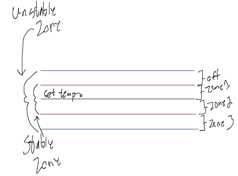
The photo above shows the basic idea.
There are 2 zones set around the set temperature. For my setup I used 1c +/- the set temp, and 10c+/- for the unstable zone.
Within each section there are zones that treat heating differently.
Off – At this zone we are well above the set temp, so the boiler is off.
Zone 1 – At this point we are above the set temp, but we also don’t want the temperature to crash down below the set temp. So if the slope of the line is negative, it applies the Zone 2 Power level, When positive it leaves the boiler off. This slows down any fall through Zone 1.
Zone 2 – This zone has a constant power level. Just enough to heat the water, but the bare minimum.
Zone 3 – This zone applies 3x more power than the 2nd zone. If I remember correctly, it’s around 40% boiler usage. This is more than enough to heat the boiler while pulling a shot. But too much to accurately control the temp with. Thus once pushed into the next zone it cuts power by quite a bit.
Below Zone 3 – This zone keeps the boiler at 100% power.
This setup allows basic temperature control. I have not looked back over it since I first set it up. I would like to add a calibration setting to the screen to figure out what values are needed for each zone. However, for now it’s working great so that’s low priority. To calibrate the values used for boiler control. I ran let the temp become stable by leaving it on for 20 minutes with proper temp control. Then I applied X boiler power and if it rose above Y point, it would subtract power and run again once the temp dropped. If it failed to go above that Y temp, it would raise the X Value. Once it settled I used that value.
Lastly, it says 106C on the pictures because the temp between the boiler and water is almost always different, due to thermal conductivity and what not. Because of that, there is about a 10c different in the water temp between the shower screen and the boiler temp. I measured that with a thermostat. But you could keep raising the temp till steam comes out, then you can assume it’s at 100c or higher. Later I will remove it. But because I’m diagnosing anything I see, I prefer to see raw data and not fluffed up data.
Next Steps
I’m happy with the current state of the project. I plan to add flow measuring for automatic control, but once that’s done I don’t know how much farther I will take it. Steam will also be added. it’s currently working but to be safe with the proto board I set the emergency cutoff temp lower than the steam temp to prevent it ever getting near thermal runaway.